
Tuabin hơi ra đời cách đây hơn 100 năm. Trong thế kỷ 19 máy hơi nước piston là máy nhiệt chủ yếu. Năm 1883 lần đầu tiên tuabin hơi được đưa vào thử nghiệm và đã nhanh chóng phát triển hơn hẳn máy hơi nước nhờ những ưu điểm sau đây :
- Công suất lớn hơn nhiều do ta sử dụng được một lượng hơi lớn không có cơ cấu trục khuỷu
- Hơi có thể giãn nở từ áp suất cao xuống áp suất rất thấp vì vậy nâng cao được hiệu suất
- Có thể thu hồi lại nước ngưng trong một chu trình nước – hơi khí nén, tăng chất lượng nước cấp với các thông số cao
- Chạy êm hơn máy hơi nước, thuận tiện trong vận hành

Gustaf de Laval 1875
Năm 1883 Gustaf de Laval ( kỹ sư người Thụy Điển ) đã chế tạo ra tuabin đầu tiên. Đây là tuabin xung lực một tầng, công suất 3,7 kW, số vòng quay rất lớn, lên đến 32.000 vòng / phút, được nối qua hộp giảm tốc với máy phát điện. Hơi đi qua ống phun dày (ống phun Laval), tăng tốc, có động năng lớn sau đó đi vào cánh quạt được gắn trên đỉnh tuabin. Tại đây động năng biến thành cơ năng làm quay trục tuabin.
Năm 1884 Charles Parsons ( Anh quốc ) đã chế tạo tuabin phản lực đầu tiên. Tuabin có công suất 5 kW, số vòng quay 18.000 vòng / phút, được nối trực tiếp với máy phát điện một chiều, áp suất hơi mới 0,7 Mpa. Đây là tuabin nhiều tầng (mỗi tầng gồm một dãy ống phun và dãy cánh động liền nhau) được gắn trực tiếp lên trục hình tang trống.

Năm 1896 Chales Curtis ( Mỹ ) đưa vào vận hành tuabin có tầng tốc độ. Trong tầng tốc độ này các cánh quạt được gắn lên cùng một đỉnh có nhiều dãy kề nhau. Nhờ đó giảm được số vòng quay và đơn giản trong truyền động.

Curtis Steam Turbine
Năm 1900 ra đời tuabin xung lực nhiều tầng đầu tiên của kỹ sư người Pháp Rateau với công suất 735 kW
Năm 1903 nhà bác học người Thụy Sỹ Aurel Stodola lần đầu tiên trình bày về lý thuyết tuabin hơi
Năm 1904 tuabin xung lực nhiều tầng và ống phun có miền cắt vát của Heinrich Zoelly ( Thụy Sỹ ), công suất 1100 kW
Năm 1907 hãng BBC ( Thụy Sỹ ) chế tạo tuabin hơi công suất 5000 kW đầu tiên với số vòng quay là 1000 Vòng/ Phút có tầng tốc độ và tầng phản lực
Năm 1912 tuabin hướng trục đầu tiên của hai anh em Ljungs Trons người Thụy Điển ra đời. Lọai tuabin hướng trục này về sau ít được phổ biến do hạn chế về công suất
Năm 1925 hãng AEG (Đức) và BBC (Thụy Điển) nâng thông số hơi lên đến P=3,5 – 5,5 MPa, nhiệt độ t = 450oC
Năm 1930 tuabin cao áp đầu tiên của thế giới ra đời do hãng BBC chế tạo với áp suất P=19,5 Mpa, t = 5000C, đây là tuabin thử nghiệm nên công suất chỉ mới đạt 4 MW
Năm 1930 tuabin hai trục với công suất 160 MW của hãng BBC và 210 MW của hãng GE, Westinghouse
Năm 1931 tuabin một trục với công suất 160 MW của hãng GE
Năm 1954 nhà máy điện nguyên tử đầu tiên ra đời ở Dbnisk (Liên xô cũ) với tuabin hơi ẩm
Năm 1956 tuabin siêu tốc với thông số hơi P = 24Mpa, t=560oC của hãng Siemens (Đức ) và GE ( Mỹ)
Năm 1960 các tuabin công suất 500 MW đầu tiên ra đời (Anh, Mỹ, Thụy Sỹ)
Năm 1970 tổ hợp tuabin – Máy phát 1000MW đầu tiên và 1300MW, tuabin hai trục của hãng BBC ra đời
Song song với việc tăng công suất các tổ máy, thông số hơi và hiệu suất của các tuabin này ngày một tăng. Trên hình sau biểu thị qúa trình phát triển của thông số hơi, hiệu suất và công suất của tổ hợp tuabin – máy phát gần một thế kỷ nay

Hình 1: Qúa trình phát triển thông số hơi, hiệu suất và công suất tuabin hơi
Ngày nay tuabin là một trong những thiết bị chính để sản xuất ra điện năng trên thế giới. Khối tuabin lớn nhất có công suất 1300 MW, thông số hơi P=16 Mpa, t = 540oC. Tuabin trong nhà máy điện nguyên tử có công suất lên đến 1500 MW. Tuy nhiên đây là tuabin hơi ẩm có P=3 - 7 Mpa, t = 300 – 310oC. Trong tương lai gần thông số của các tuabin sẽ lên đến 35 Mpa/700oC. Bên cạnh đó việc tăng độ tin cậy và khả năng vận hành an toàn của các tuabin cũng được quan tâm. Để giảm giá thành và giảm ô nhiễm môi trường cần thiết phải nâng cao hiệu suất của các nhà máy nhiệt điện. Ngày nay hiệu suất này có thể lên đến 35 – 45%. Một trong những biện pháp thích hợp nhất để nâng cao hiệu suất là thực hiện sản xuất phối hợp điện nhiệt năng và chu trình hỗn hợp khí – hơi
Hiện nay các hãng chế tạo tuabin trên thế giới có rất nhiều, trong đó đáng kể là ABB (Thụy sỹ), Siemens (Đức), GE (Mỹ), LMZ (Nga), Skoda (Sec)… Việt nam hiện nay chưa chế tạo được tuabin. Vào đầu những năm 1970 đã có dự định xây dựng nhà máy chế tạo tuabin, đã cử người đi thực tập ở các nước XHCN lúc bấy giờ. Tuy vậy do hoàn cảnh chiến tranh, trình độ kỹ thuật lạc hậu và nền kinh tế yếu kém, dự án này không thực hiện được. Những tuabin đầu tiên ở nước ta được nhập từ thời Pháp, công suất từ 1 – 5 MW, sau năm 1954 ở miền bắc đã có các tuabin trung áp của Liên Xô (cũ), Trung quốc, công suất từ 6 – 50 MW. Gần đây đã có các tổ máy 66 MW và 110 MW ở Thủ đức và Phả Lại. Tuy nhiên so với thế giới các tuabin này rất nhỏ bé, lạc hậu
Steam Turbine
Steam turbine
From Wikipedia, the free encyclopedia
A steam turbine is a mechanical device that extracts thermal energy from pressurized steam, and converts it into rotary motion. Its modern manifestation was invented by Sir Charles Parsons in 1884.[1]
It has almost completely replaced the reciprocating piston steam engine primarily because of its greater thermal efficiency and higher power-to-weight ratio. Because the turbine generates rotary motion, it is particularly suited to be used to drive an electrical generator – about 80% of all electricity generation in the world is by use of steam turbines. The steam turbine is a form of heat engine that derives much of its improvement in thermodynamic efficiency through the use of multiple stages in the expansion of the steam, which results in a closer approach to the ideal reversible process.
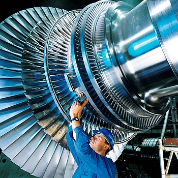

A rotor of a modern steam turbine, used in a power plant
History

2000 KW Curtis steam turbine circa 1905.
The first device that may be classified as a reaction steam turbine was little more than a toy, the classic Aeolipile, described in the 1st century by Hero of Alexandria in Roman Egypt.[2][3][4] More than a thousand years later, in 1551, Taqi al-Din in Ottoman Egypt described a steam turbine with the practical application of rotating a spit. Steam turbines were also described by the Italian Giovanni Branca (1629) and John Wilkins in England (1648.)[5]

Parsons turbine from the Polish destroyer ORP Wicher II
The modern steam turbine was invented in 1884 by the Englishman Sir Charles Parsons, whose first model was connected to a dynamo that generated 7.5 kW of electricity.[6] After the invention of Parson's steam turbine, which made cheap and plentiful electricity possible and revolutionised marine transport and naval warfare, the world would never be the same again.[7] His patent was licensed and the turbine scaled-up shortly after by an American, George Westinghouse. The Parson's turbine also turned out to be easy to scale-up. Parsons had the satisfaction of seeing his invention adopted for all major world power stations, and the size of generators had increased from his first 7.5 kW set up to units of 50,000 kW capacity. Within Parson's lifetime the generating capacity of a unit was scaled-up by about 10,000 times,[8] and the total output from turbo-generators constructed by his firm C. A. Parsons and Company and by their licensees, for land purposes alone, had exceeded thirty million horse-power.[6]
A number of other variations of turbines have been developed that work effectively with steam. The de Laval turbine (invented by Gustaf de Laval) accelerated the steam to full speed before running it against a turbine blade. Hence the (impulse) turbine is simpler, less expensive and does not need to be pressure-proof. It can operate with any pressure of steam, but is considerably less efficient.
The Brown-Curtis turbine which had been originally developed and patented by the U.S. company International Curtis Marine Turbine Company was developed in the 1900s in conjunction with John Brown & Company. It was used in John Brown's merchant ships and warships, including liners and Royal Navy warships.
For the types of steam turbine, including the Rateau multistage see Leander Project.
Types
Steam turbines are made in a variety of sizes ranging from small 1 hp (0.75 kW) units (rare) used as mechanical drives for pumps, compressors and other shaft driven equipment, to 2,000,000 hp (1,500,000 kW) turbines used to generate electricity. There are several classifications for modern steam turbines.
Steam Supply and Exhaust Conditions
These types include condensing, noncondensing, reheat, extraction and induction.
Noncondensing or backpressure turbines are most widely used for process steam applications. The exhaust pressure is controlled by a regulating valve to suit the needs of the process steam pressure. These are commonly found at refineries, district heating units, pulp and paper plants, and desalination facilities where large amounts of low pressure process steam are available.
Condensing turbines are most commonly found in electrical power plants. These turbines exhaust steam in a partially condensed state, typically of a quality near 90%, at a pressure well below atmospheric to a condenser.
Reheat turbines are also used almost exclusively in electrical power plants. In a reheat turbine, steam flow exits from a high pressure section of the turbine and is returned to the boiler where additional superheat is added. The steam then goes back into an intermediate pressure section of the turbine and continues its expansion.
Extracting type turbines are common in all applications. In an extracting type turbine, steam is released from various stages of the turbine, and used for industrial process needs or sent to boiler feedwater heaters to improve overall cycle efficiency. Extraction flows may be controlled with a valve, or left uncontrolled.
Induction turbines introduce low pressure steam at an intermediate stage to produce additional power.
Casing or Shaft Arrangements
These arrangements include single casing, tandem compound and cross compound turbines. Single casing units are the most basic style where a single casing and shaft are coupled to a generator. Tandem compound are used where two or more casings are directly coupled together to drive a single generator. A cross compound turbine arrangement features two or more shafts not in line driving two or more generators that often operate at different speeds. A cross compound turbine is typically used for many large applications.
Principle of Operation and Design
An ideal steam turbine is considered to be an isentropic process, or constant entropy process, in which the entropy of the steam entering the turbine is equal to the entropy of the steam leaving the turbine. No steam turbine is truly “isentropic”, however, with typical isentropic efficiencies ranging from 20%-90% based on the application of the turbine. The interior of a turbine comprises several sets of blades, or “buckets” as they are more commonly referred to. One set of stationary blades is connected to the casing and one set of rotating blades is connected to the shaft. The sets intermesh with certain minimum clearances, with the size and configuration of sets varying to efficiently exploit the expansion of steam at each stage.
Turbine efficiency

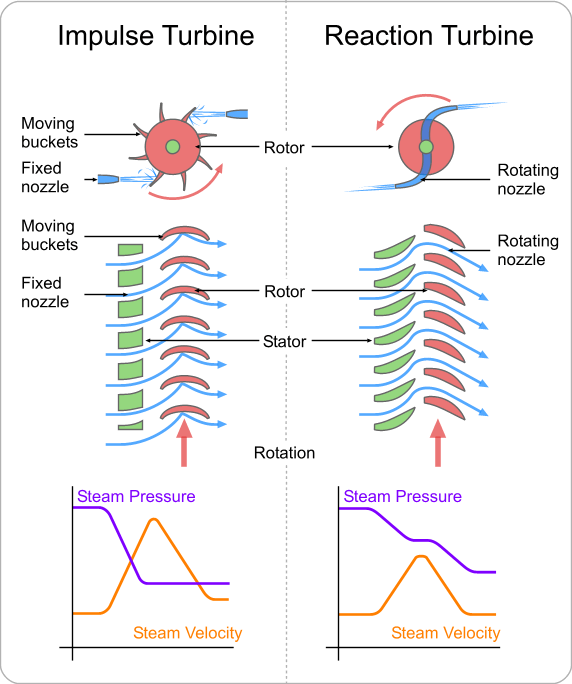
Schematic diagram outlining the difference between an impulse and a reaction turbine
To maximize turbine efficiency the steam is expanded, generating work, in a number of stages. These stages are characterized by how the energy is extracted from them and are known as either impulse or reaction turbines. Most steam turbines use a mixture of the reaction and impulse designs: each stage behaves as either one or the other, but the overall turbine uses both. Typically, higher pressure sections are impulse type and lower pressure stages are reaction type.
Impulse turbines
An impulse turbine has fixed nozzles that orient the steam flow into high speed jets. These jets contain significant kinetic energy, which the rotor blades, shaped like buckets, convert into shaft rotation as the steam jet changes direction. A pressure drop occurs across only the stationary blades, with a net increase in steam velocity across the stage.
As the steam flows through the nozzle its pressure falls from inlet pressure to the exit pressure (atmospheric pressure, or more usually, the condenser vacuum). Due to this higher ratio of expansion of steam in the nozzle the steam leaves the nozzle with a very high velocity. The steam leaving the moving blades is a large portion of the maximum velocity of the steam when leaving the nozzle. The loss of energy due to this higher exit velocity is commonly called the "carry over velocity" or "leaving loss".
Reaction turbines
In the reaction turbine, the rotor blades themselves are arranged to form convergent nozzles. This type of turbine makes use of the reaction force produced as the steam accelerates through the nozzles formed by the rotor. Steam is directed onto the rotor by the fixed vanes of the stator. It leaves the stator as a jet that fills the entire circumference of the rotor. The steam then changes direction and increases its speed relative to the speed of the blades. A pressure drop occurs across both the stator and the rotor, with steam accelerating through the stator and decelerating through the rotor, with no net change in steam velocity across the stage but with a decrease in both pressure and temperature, reflecting the work performed in the driving of the rotor.
Operation and Maintenance
When warming up a steam turbine for use, the main steam stop valves (after the boiler) have a bypass line to allow superheated steam to slowly bypass the valve and proceed to heat up the lines in the system along with the steam turbine. Also a turning gear is engaged when there is no steam to the turbine to slowly rotate the turbine to ensure even heating to prevent uneven expansion. After first rotating the turbine by the turning gear, allowing time for the rotor to assume a straight plane (no bowing), then the turning gear is disengaged and steam is admitted to the turbine, first to the astern blades then to the ahead blades slowly rotating the turbine at 10 to 15 RPM to slowly warm the turbine.
Problems with turbines are now rare and maintenance requirements are relatively small. Any imbalance of the rotor can lead to vibration, which in extreme cases can lead to a blade letting go and punching straight through the casing. It is, however, essential that the turbine be turned with dry steam. If water gets into the steam and is blasted onto the blades (moisture carryover) rapid impingement and erosion of the blades can occur, possibly leading to imbalance and catastrophic failure. Also, water entering the blades will likely result in the destruction of the thrust bearing for the turbine shaft. To prevent this, along with controls and baffles in the boilers to ensure high quality steam, condensate drains are installed in the steam piping leading to the turbine.
Speed regulation
The control of a turbine with a governor is essential, as turbines need to be run up slowly, to prevent damage while some applications (such as the generation of alternating current electricity) require precise speed control.[9] Uncontrolled acceleration of the turbine rotor can lead to an overspeed trip, which causes the nozzle valves that control the flow of steam to the turbine to close. If this fails then the turbine may continue accelerating until it breaks apart, often spectacularly. Turbines are expensive to make, requiring precision manufacture and special quality materials. During normal operation in synchronization with the electricity net powerplants are governed with a five percent droop speed control . This means the full load speed is 100% and the no load speed is 105%. This is required for the stable operation of the net without hunting and dropouts of powerplants. Normally the changes in speed are minor . Adjustments in power output are made by slowly raising the droop curve by increasing the spring pressure on a centrifugal governor. Generally this is a basic system requirement for all powerplants because the older and newer plants have to be compatible in response to the instantaneous changes inDirect driveElectrical power stations use large steam turbines driving electric generators to produce most (about 80%) of the world's electricity. Most of these centralised stations are of two types, fossil fuel power plants and nuclear power plants, but some countries are using concentrating solar power (CSP) to create the steam. Steam turbines can also be used directly to drive large centrifugal pumps, such as feedwater pumps at a thermal power plant.
It has been proposed[11] that, given sufficient solar energy, silicon might be refined for use as a coal replacement for this type of engine.
The turbines used for electric power generation are most often directly coupled to their generators. As the generators must rotate at constant synchronous speeds according to the frequency of the electric power system, the most common speeds are 3000 r/min for 50 Hz systems, and 3600 r/min for 60 Hz systems. In installations with high steam output, as may be found in nuclear power stations, the generator sets may be arranged to operate at half these speeds, but with four-pole generators.[12]
Marine propulsion

The Turbinia - the first steam turbine-powered ship
Another use of steam turbines is in ships; their small size, low maintenance, light weight, and low vibration are compelling advantages. A steam turbine is only efficient when operating in the thousands of RPM, while the most effective propeller designs are for speeds less than 100 RPM. Therefore precise (thus expensive) reduction gears are generally used, although several ships, such as Turbinia, had direct drive from the steam turbine to the propeller shafts. The purchase cost is offset by much lower fuel and maintenance requirements and the small size of a turbine when compared to a reciprocating engine having an equivalent power. However, diesel engines are capable of higher efficiencies: steam turbine cycle efficiencies have yet to break 50%, yet diesel engines routinely exceed 50%, especially in marine applications.[13][14] [15] [16]
Nuclear-powered ships and submarines use a nuclear reactor to create steam and either use a steam turbine directly for main propulsion, with generators providing auxiliary power, or else employ turbo-electric propulsion, where the steam drives a turbine-generator set with propulsion provided by electric motors. Nuclear power is often chosen where diesel power would be impractical (as in submarine applications) or the logistics of refuelling pose significant problems (for example, icebreakers). It has been estimated that the reactor fuel for the Royal Navy's Vanguard class submarine is sufficient to last 40 circumnavigations of the globe – potentially sufficient for the vessel's entire service life.
Locomotives
Main article: Steam turbine locomotive
A steam turbine locomotive engine is a steam locomotive driven by a steam turbine.
The main advantage of a steam turbine locomotive is better balance and reduced hammer blow on the track. However, a disadvantage is that its output power is less flexible and so turbine locomotives were best suited for long-haul operations at a constant output power.[17]
The first steam turbine locomotive was built in 1908 for the Officine Mecaniche Miani Silvestri Grodona Comi in Milan. For the German National Railroad company Krupp built in 1924 the steam turbine locomotive T18 001, which was operational in 1929.
THEO NGUỒN WIKIMEDIA
- Công suất lớn hơn nhiều do ta sử dụng được một lượng hơi lớn không có cơ cấu trục khuỷu
- Hơi có thể giãn nở từ áp suất cao xuống áp suất rất thấp vì vậy nâng cao được hiệu suất
- Có thể thu hồi lại nước ngưng trong một chu trình nước – hơi khí nén, tăng chất lượng nước cấp với các thông số cao
- Chạy êm hơn máy hơi nước, thuận tiện trong vận hành
Gustaf de Laval 1875
Năm 1884 Charles Parsons ( Anh quốc ) đã chế tạo tuabin phản lực đầu tiên. Tuabin có công suất 5 kW, số vòng quay 18.000 vòng / phút, được nối trực tiếp với máy phát điện một chiều, áp suất hơi mới 0,7 Mpa. Đây là tuabin nhiều tầng (mỗi tầng gồm một dãy ống phun và dãy cánh động liền nhau) được gắn trực tiếp lên trục hình tang trống.
Tuabin xung lực thiết kế bởi Gustaf de Laval - Impulse Turbine by Gustaf de Laval. Built in Sweden, 1888. Deutsches Museum, Munich.
Curtis Steam Turbine
Năm 1903 nhà bác học người Thụy Sỹ Aurel Stodola lần đầu tiên trình bày về lý thuyết tuabin hơi
Năm 1904 tuabin xung lực nhiều tầng và ống phun có miền cắt vát của Heinrich Zoelly ( Thụy Sỹ ), công suất 1100 kW
Năm 1907 hãng BBC ( Thụy Sỹ ) chế tạo tuabin hơi công suất 5000 kW đầu tiên với số vòng quay là 1000 Vòng/ Phút có tầng tốc độ và tầng phản lực
Năm 1912 tuabin hướng trục đầu tiên của hai anh em Ljungs Trons người Thụy Điển ra đời. Lọai tuabin hướng trục này về sau ít được phổ biến do hạn chế về công suất
Năm 1925 hãng AEG (Đức) và BBC (Thụy Điển) nâng thông số hơi lên đến P=3,5 – 5,5 MPa, nhiệt độ t = 450oC
Năm 1930 tuabin cao áp đầu tiên của thế giới ra đời do hãng BBC chế tạo với áp suất P=19,5 Mpa, t = 5000C, đây là tuabin thử nghiệm nên công suất chỉ mới đạt 4 MW
Năm 1930 tuabin hai trục với công suất 160 MW của hãng BBC và 210 MW của hãng GE, Westinghouse
Năm 1931 tuabin một trục với công suất 160 MW của hãng GE
Năm 1954 nhà máy điện nguyên tử đầu tiên ra đời ở Dbnisk (Liên xô cũ) với tuabin hơi ẩm
Năm 1956 tuabin siêu tốc với thông số hơi P = 24Mpa, t=560oC của hãng Siemens (Đức ) và GE ( Mỹ)
Năm 1960 các tuabin công suất 500 MW đầu tiên ra đời (Anh, Mỹ, Thụy Sỹ)
Năm 1970 tổ hợp tuabin – Máy phát 1000MW đầu tiên và 1300MW, tuabin hai trục của hãng BBC ra đời
Song song với việc tăng công suất các tổ máy, thông số hơi và hiệu suất của các tuabin này ngày một tăng. Trên hình sau biểu thị qúa trình phát triển của thông số hơi, hiệu suất và công suất của tổ hợp tuabin – máy phát gần một thế kỷ nay
Hình 1: Qúa trình phát triển thông số hơi, hiệu suất và công suất tuabin hơi
Ngày nay tuabin là một trong những thiết bị chính để sản xuất ra điện năng trên thế giới. Khối tuabin lớn nhất có công suất 1300 MW, thông số hơi P=16 Mpa, t = 540oC. Tuabin trong nhà máy điện nguyên tử có công suất lên đến 1500 MW. Tuy nhiên đây là tuabin hơi ẩm có P=3 - 7 Mpa, t = 300 – 310oC. Trong tương lai gần thông số của các tuabin sẽ lên đến 35 Mpa/700oC. Bên cạnh đó việc tăng độ tin cậy và khả năng vận hành an toàn của các tuabin cũng được quan tâm. Để giảm giá thành và giảm ô nhiễm môi trường cần thiết phải nâng cao hiệu suất của các nhà máy nhiệt điện. Ngày nay hiệu suất này có thể lên đến 35 – 45%. Một trong những biện pháp thích hợp nhất để nâng cao hiệu suất là thực hiện sản xuất phối hợp điện nhiệt năng và chu trình hỗn hợp khí – hơi
Hiện nay các hãng chế tạo tuabin trên thế giới có rất nhiều, trong đó đáng kể là ABB (Thụy sỹ), Siemens (Đức), GE (Mỹ), LMZ (Nga), Skoda (Sec)… Việt nam hiện nay chưa chế tạo được tuabin. Vào đầu những năm 1970 đã có dự định xây dựng nhà máy chế tạo tuabin, đã cử người đi thực tập ở các nước XHCN lúc bấy giờ. Tuy vậy do hoàn cảnh chiến tranh, trình độ kỹ thuật lạc hậu và nền kinh tế yếu kém, dự án này không thực hiện được. Những tuabin đầu tiên ở nước ta được nhập từ thời Pháp, công suất từ 1 – 5 MW, sau năm 1954 ở miền bắc đã có các tuabin trung áp của Liên Xô (cũ), Trung quốc, công suất từ 6 – 50 MW. Gần đây đã có các tổ máy 66 MW và 110 MW ở Thủ đức và Phả Lại. Tuy nhiên so với thế giới các tuabin này rất nhỏ bé, lạc hậu
Steam Turbine
Steam turbine
From Wikipedia, the free encyclopedia
A steam turbine is a mechanical device that extracts thermal energy from pressurized steam, and converts it into rotary motion. Its modern manifestation was invented by Sir Charles Parsons in 1884.[1]
It has almost completely replaced the reciprocating piston steam engine primarily because of its greater thermal efficiency and higher power-to-weight ratio. Because the turbine generates rotary motion, it is particularly suited to be used to drive an electrical generator – about 80% of all electricity generation in the world is by use of steam turbines. The steam turbine is a form of heat engine that derives much of its improvement in thermodynamic efficiency through the use of multiple stages in the expansion of the steam, which results in a closer approach to the ideal reversible process.
A rotor of a modern steam turbine, used in a power plant
History
2000 KW Curtis steam turbine circa 1905.
The first device that may be classified as a reaction steam turbine was little more than a toy, the classic Aeolipile, described in the 1st century by Hero of Alexandria in Roman Egypt.[2][3][4] More than a thousand years later, in 1551, Taqi al-Din in Ottoman Egypt described a steam turbine with the practical application of rotating a spit. Steam turbines were also described by the Italian Giovanni Branca (1629) and John Wilkins in England (1648.)[5]
Parsons turbine from the Polish destroyer ORP Wicher II
The modern steam turbine was invented in 1884 by the Englishman Sir Charles Parsons, whose first model was connected to a dynamo that generated 7.5 kW of electricity.[6] After the invention of Parson's steam turbine, which made cheap and plentiful electricity possible and revolutionised marine transport and naval warfare, the world would never be the same again.[7] His patent was licensed and the turbine scaled-up shortly after by an American, George Westinghouse. The Parson's turbine also turned out to be easy to scale-up. Parsons had the satisfaction of seeing his invention adopted for all major world power stations, and the size of generators had increased from his first 7.5 kW set up to units of 50,000 kW capacity. Within Parson's lifetime the generating capacity of a unit was scaled-up by about 10,000 times,[8] and the total output from turbo-generators constructed by his firm C. A. Parsons and Company and by their licensees, for land purposes alone, had exceeded thirty million horse-power.[6]
A number of other variations of turbines have been developed that work effectively with steam. The de Laval turbine (invented by Gustaf de Laval) accelerated the steam to full speed before running it against a turbine blade. Hence the (impulse) turbine is simpler, less expensive and does not need to be pressure-proof. It can operate with any pressure of steam, but is considerably less efficient.
The Brown-Curtis turbine which had been originally developed and patented by the U.S. company International Curtis Marine Turbine Company was developed in the 1900s in conjunction with John Brown & Company. It was used in John Brown's merchant ships and warships, including liners and Royal Navy warships.
For the types of steam turbine, including the Rateau multistage see Leander Project.
Types
Steam turbines are made in a variety of sizes ranging from small 1 hp (0.75 kW) units (rare) used as mechanical drives for pumps, compressors and other shaft driven equipment, to 2,000,000 hp (1,500,000 kW) turbines used to generate electricity. There are several classifications for modern steam turbines.
Steam Supply and Exhaust Conditions
These types include condensing, noncondensing, reheat, extraction and induction.
Noncondensing or backpressure turbines are most widely used for process steam applications. The exhaust pressure is controlled by a regulating valve to suit the needs of the process steam pressure. These are commonly found at refineries, district heating units, pulp and paper plants, and desalination facilities where large amounts of low pressure process steam are available.
Condensing turbines are most commonly found in electrical power plants. These turbines exhaust steam in a partially condensed state, typically of a quality near 90%, at a pressure well below atmospheric to a condenser.
Reheat turbines are also used almost exclusively in electrical power plants. In a reheat turbine, steam flow exits from a high pressure section of the turbine and is returned to the boiler where additional superheat is added. The steam then goes back into an intermediate pressure section of the turbine and continues its expansion.
Extracting type turbines are common in all applications. In an extracting type turbine, steam is released from various stages of the turbine, and used for industrial process needs or sent to boiler feedwater heaters to improve overall cycle efficiency. Extraction flows may be controlled with a valve, or left uncontrolled.
Induction turbines introduce low pressure steam at an intermediate stage to produce additional power.
Casing or Shaft Arrangements
These arrangements include single casing, tandem compound and cross compound turbines. Single casing units are the most basic style where a single casing and shaft are coupled to a generator. Tandem compound are used where two or more casings are directly coupled together to drive a single generator. A cross compound turbine arrangement features two or more shafts not in line driving two or more generators that often operate at different speeds. A cross compound turbine is typically used for many large applications.
Principle of Operation and Design
An ideal steam turbine is considered to be an isentropic process, or constant entropy process, in which the entropy of the steam entering the turbine is equal to the entropy of the steam leaving the turbine. No steam turbine is truly “isentropic”, however, with typical isentropic efficiencies ranging from 20%-90% based on the application of the turbine. The interior of a turbine comprises several sets of blades, or “buckets” as they are more commonly referred to. One set of stationary blades is connected to the casing and one set of rotating blades is connected to the shaft. The sets intermesh with certain minimum clearances, with the size and configuration of sets varying to efficiently exploit the expansion of steam at each stage.
Turbine efficiency
Schematic diagram outlining the difference between an impulse and a reaction turbine
To maximize turbine efficiency the steam is expanded, generating work, in a number of stages. These stages are characterized by how the energy is extracted from them and are known as either impulse or reaction turbines. Most steam turbines use a mixture of the reaction and impulse designs: each stage behaves as either one or the other, but the overall turbine uses both. Typically, higher pressure sections are impulse type and lower pressure stages are reaction type.
Impulse turbines
An impulse turbine has fixed nozzles that orient the steam flow into high speed jets. These jets contain significant kinetic energy, which the rotor blades, shaped like buckets, convert into shaft rotation as the steam jet changes direction. A pressure drop occurs across only the stationary blades, with a net increase in steam velocity across the stage.
As the steam flows through the nozzle its pressure falls from inlet pressure to the exit pressure (atmospheric pressure, or more usually, the condenser vacuum). Due to this higher ratio of expansion of steam in the nozzle the steam leaves the nozzle with a very high velocity. The steam leaving the moving blades is a large portion of the maximum velocity of the steam when leaving the nozzle. The loss of energy due to this higher exit velocity is commonly called the "carry over velocity" or "leaving loss".
Reaction turbines
In the reaction turbine, the rotor blades themselves are arranged to form convergent nozzles. This type of turbine makes use of the reaction force produced as the steam accelerates through the nozzles formed by the rotor. Steam is directed onto the rotor by the fixed vanes of the stator. It leaves the stator as a jet that fills the entire circumference of the rotor. The steam then changes direction and increases its speed relative to the speed of the blades. A pressure drop occurs across both the stator and the rotor, with steam accelerating through the stator and decelerating through the rotor, with no net change in steam velocity across the stage but with a decrease in both pressure and temperature, reflecting the work performed in the driving of the rotor.
Operation and Maintenance
When warming up a steam turbine for use, the main steam stop valves (after the boiler) have a bypass line to allow superheated steam to slowly bypass the valve and proceed to heat up the lines in the system along with the steam turbine. Also a turning gear is engaged when there is no steam to the turbine to slowly rotate the turbine to ensure even heating to prevent uneven expansion. After first rotating the turbine by the turning gear, allowing time for the rotor to assume a straight plane (no bowing), then the turning gear is disengaged and steam is admitted to the turbine, first to the astern blades then to the ahead blades slowly rotating the turbine at 10 to 15 RPM to slowly warm the turbine.
Problems with turbines are now rare and maintenance requirements are relatively small. Any imbalance of the rotor can lead to vibration, which in extreme cases can lead to a blade letting go and punching straight through the casing. It is, however, essential that the turbine be turned with dry steam. If water gets into the steam and is blasted onto the blades (moisture carryover) rapid impingement and erosion of the blades can occur, possibly leading to imbalance and catastrophic failure. Also, water entering the blades will likely result in the destruction of the thrust bearing for the turbine shaft. To prevent this, along with controls and baffles in the boilers to ensure high quality steam, condensate drains are installed in the steam piping leading to the turbine.
Speed regulation
The control of a turbine with a governor is essential, as turbines need to be run up slowly, to prevent damage while some applications (such as the generation of alternating current electricity) require precise speed control.[9] Uncontrolled acceleration of the turbine rotor can lead to an overspeed trip, which causes the nozzle valves that control the flow of steam to the turbine to close. If this fails then the turbine may continue accelerating until it breaks apart, often spectacularly. Turbines are expensive to make, requiring precision manufacture and special quality materials. During normal operation in synchronization with the electricity net powerplants are governed with a five percent droop speed control . This means the full load speed is 100% and the no load speed is 105%. This is required for the stable operation of the net without hunting and dropouts of powerplants. Normally the changes in speed are minor . Adjustments in power output are made by slowly raising the droop curve by increasing the spring pressure on a centrifugal governor. Generally this is a basic system requirement for all powerplants because the older and newer plants have to be compatible in response to the instantaneous changes inDirect driveElectrical power stations use large steam turbines driving electric generators to produce most (about 80%) of the world's electricity. Most of these centralised stations are of two types, fossil fuel power plants and nuclear power plants, but some countries are using concentrating solar power (CSP) to create the steam. Steam turbines can also be used directly to drive large centrifugal pumps, such as feedwater pumps at a thermal power plant.
It has been proposed[11] that, given sufficient solar energy, silicon might be refined for use as a coal replacement for this type of engine.
The turbines used for electric power generation are most often directly coupled to their generators. As the generators must rotate at constant synchronous speeds according to the frequency of the electric power system, the most common speeds are 3000 r/min for 50 Hz systems, and 3600 r/min for 60 Hz systems. In installations with high steam output, as may be found in nuclear power stations, the generator sets may be arranged to operate at half these speeds, but with four-pole generators.[12]
Marine propulsion
The Turbinia - the first steam turbine-powered ship
Another use of steam turbines is in ships; their small size, low maintenance, light weight, and low vibration are compelling advantages. A steam turbine is only efficient when operating in the thousands of RPM, while the most effective propeller designs are for speeds less than 100 RPM. Therefore precise (thus expensive) reduction gears are generally used, although several ships, such as Turbinia, had direct drive from the steam turbine to the propeller shafts. The purchase cost is offset by much lower fuel and maintenance requirements and the small size of a turbine when compared to a reciprocating engine having an equivalent power. However, diesel engines are capable of higher efficiencies: steam turbine cycle efficiencies have yet to break 50%, yet diesel engines routinely exceed 50%, especially in marine applications.[13][14] [15] [16]
Nuclear-powered ships and submarines use a nuclear reactor to create steam and either use a steam turbine directly for main propulsion, with generators providing auxiliary power, or else employ turbo-electric propulsion, where the steam drives a turbine-generator set with propulsion provided by electric motors. Nuclear power is often chosen where diesel power would be impractical (as in submarine applications) or the logistics of refuelling pose significant problems (for example, icebreakers). It has been estimated that the reactor fuel for the Royal Navy's Vanguard class submarine is sufficient to last 40 circumnavigations of the globe – potentially sufficient for the vessel's entire service life.
Locomotives
Main article: Steam turbine locomotive
A steam turbine locomotive engine is a steam locomotive driven by a steam turbine.
The main advantage of a steam turbine locomotive is better balance and reduced hammer blow on the track. However, a disadvantage is that its output power is less flexible and so turbine locomotives were best suited for long-haul operations at a constant output power.[17]
The first steam turbine locomotive was built in 1908 for the Officine Mecaniche Miani Silvestri Grodona Comi in Milan. For the German National Railroad company Krupp built in 1924 the steam turbine locomotive T18 001, which was operational in 1929.
THEO NGUỒN WIKIMEDIA