

linhautonet
Tài xế O-H
I received a lot of request from friends to teach them about surface modeling in CATIA V5. In this tutorial I will demonstrate how to use the Generative Shape Design workbench to create an F1 front wing. I will not make it in real scale as I don't have any dimension with me.
Start the workbench by selecting Start > Shape> Generative Shape Design. A dialogue box will appear for you to name your part. Rename the part as F1FrontWing or any name you want and click the OK button. Then your part will be created and you are now in the Generative Shape Design workbench.

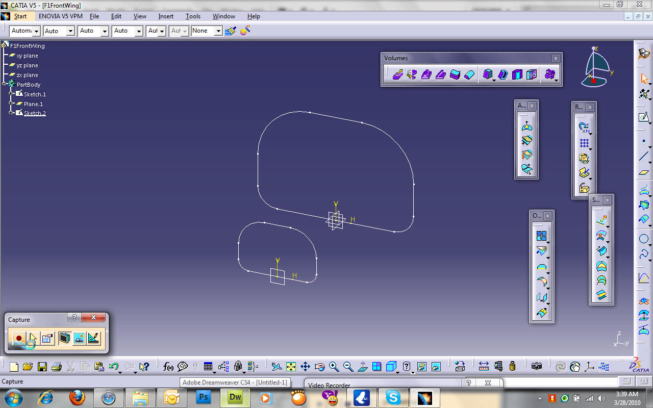
Select the yz-plane and click on the Sketcher Tool icon. In the Sketcher workbench create a drawing of dimensions as shown in the figure below:

Once the drawing has been created, go back to the Generative Shape Design workbench. Create a plane using the Insert Plane icon or select Insert > Wireframe > Plane. In the Plane Definition box select Offset from plane for the Plane type, yz-plane as the Reference plane, and 100mm Offset as shown in the figure:

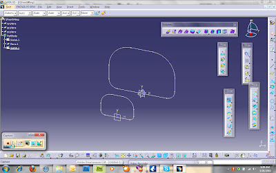
Now you have a new plane. To make things simple, we will copy the previous drawing and paste it on the new frame. To do this, double-click on the Sketch.1 in the design tree to open the 1st drawing in the Sketcher workbench. Select all the lines and curves and copy them (ctrl+c). Then exit the Sketcher workbench, select the new plane you had just created, click on the Sketcher tool icon, and paste (ctrl+v) on it. After the drawing had been pasted, what we will do next is to resize all the dimensions to half of their current values. Note that while doing this the 1st drawing also appears in the background so it is advisable for you to hide it. See the next figure:

After done with the second drawing, exit the Sketcher workbench. Now you should have 2 profiles.
Next is to fill in some shape to the profiles. I will not make this as beautiful as a regular F1 wing look like. First is to connect both profiles together and create the basic shape. I will use the Blend tool for this. The Blend tool is on the Surface toolbar. Select the Blend tool and in the Blend Definition box, select the first sketch (Sketch.1) for First curve and Sketch.2 for Second curve. Then press Preview to take a look at the generated shape and press OK when you are satisfied.

Now we shall close the front hole using the Fill tool which is also on the Surface toolbar. In the Fill Definition box select Sketch.2 for Curves and Blend.1 for Support, and select Tangent for Continuity. Then press Preview. The fill is now generated. Try change the Continuity to Point and press Preview and you will see what is meant by Continuity.

We will need to combine these two surfaces by using the Join tool which is on the Operations toolbar or you can select Insert > Operations > Join. In the Join Definition box select Blend.1 and Fill.1 as the Elements To Join and press OK. After joining them together, the Blend.1 and Fill.1 is now combined to be 1 surface of Join.1.
You can now hide Sketch.1 and Sketch.2 before we go to the next step. What we have created is a shape. The problem for some people is that they know how to create such shapes but didn't know how to convert them into parts like those you created using Part Design Workbench. To create a part out of this shape, we will need to go to the Part Design Workbench. Select Start > Mechanical Design > Part Design. Make sure you are not creating a new part but still using the same part in different workbench. Click on the Thick Surface tool or select Insert > Surface-Based Features > Thick Surface. In the ThickSurface Definition box, select Join.1 as the Object to offset, set the First Offset to be 2mm and Second Offset to be 1mm. Press Preview to see the changes. After pressing OK, a part is created base on the shape you had designed. You can now hide Join.1.

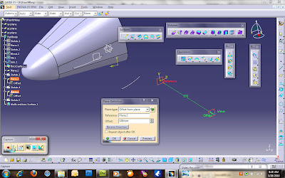
What we have created is just the nose. Now go back to the Generative Shape Design workbench to create the wing. Create a plane using the Create Plane tool then in the Plane Definition box select Plane Type to be Tangent to Surface. For the Surface and Point, select the face and point as shown in the figure below. Click Preview then drag the point to about the center of the face before pressing OK.

Select the new plane and click on the Sketcher tool. Draw an curve using the Spline tool.

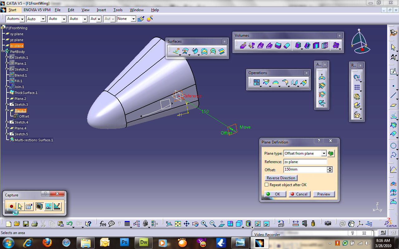
Now create another plane. In the Plane Definition box, select the Plane Type to be Offset from plane. Select the zx-plane to be the Reference plane and the Offset to be 150mm.

In the design tree you will see the new plane is named Plane.3. Select this plane and click on the Sketcher tool. Then create another curve as similar to the one you draw prevously but with smaller dimension as shown in the figure:

Then create another plane similar to Plane.3 but this time the Reference plane is Plane.3. The Offset is still 150mm.
Create another curve profile but smaller that the second curve

After you exit the Sketcher workbench there will be 3 curve profiles.
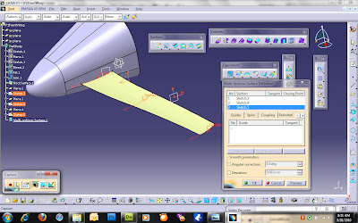
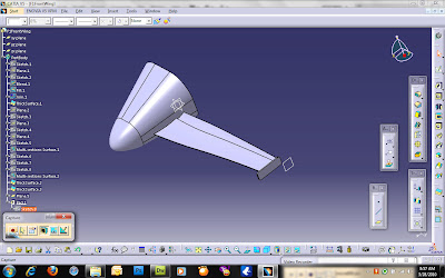
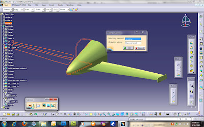
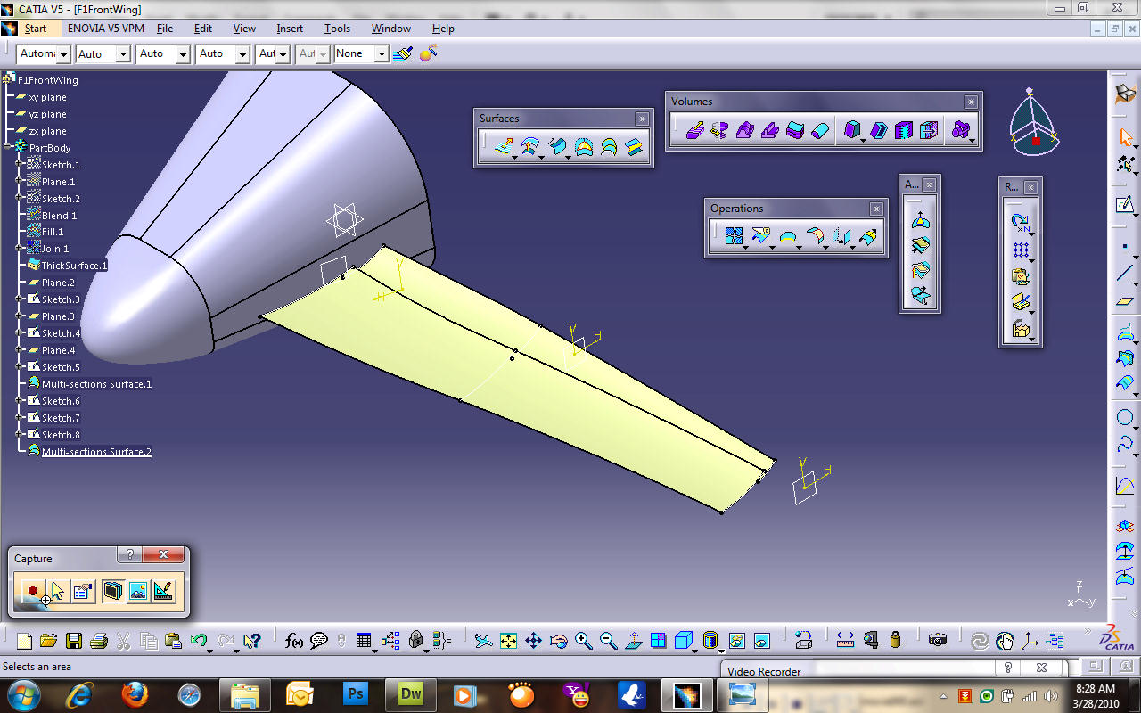
Next we are going to create a shape out of the 3 profiles using Multi-Sections Surface tool in the Surface toolbar. In the Multi-Sections Surface Definition box, select the 3 curve profiles (Sketch.3, Sketch.4 and Sketch.5). Before pressing Preview, check the arrows that appeared on each profiles. They all should be on the same direction or the shape cannot be generated. Click on arrows that is pointing the other direction to change its direction. Once all the arrows are pointing in the same direction, press the Preview button. If your shape is generated and no error message appeared then press OK.
To make it look better I will add another layer of surface for the wing similar method as before.
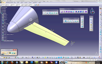
Next we are going to make plates out of these wing shapes. Go to the Part Design Workbench and use the Thick Profile tool just as we did previously. Set the 1st Offset to be 1mm while 2nd Offset to be 0mm. For the second plate, set the 1st Offset to be 0mm and 2nd Offset to be 1mm. This is to prevent the two wing plates from being joined together.

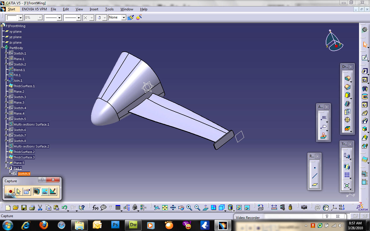
To add some pretty finish to the wing. Create a plane 300mm Offset from the zx-plane. Then make something like in the figure using Sketcher and Pad.
When I try to Mirror this part a problem occured because the nose is a complete part. To solve this we need to cut the nose into half. The task is to use the Pocket tool. Select the yz-plane and create a big box to cut the nose part using the Pocket tool.

Next is to Mirror the part using the Mirror tool and select the zx-plane the Mirroring element.
nguồn : catiatutorial.blogspot.com
http://creativecommons.org/licenses/by-nc/3.0
Start the workbench by selecting Start > Shape> Generative Shape Design. A dialogue box will appear for you to name your part. Rename the part as F1FrontWing or any name you want and click the OK button. Then your part will be created and you are now in the Generative Shape Design workbench.

Select the yz-plane and click on the Sketcher Tool icon. In the Sketcher workbench create a drawing of dimensions as shown in the figure below:

Once the drawing has been created, go back to the Generative Shape Design workbench. Create a plane using the Insert Plane icon or select Insert > Wireframe > Plane. In the Plane Definition box select Offset from plane for the Plane type, yz-plane as the Reference plane, and 100mm Offset as shown in the figure:

Now you have a new plane. To make things simple, we will copy the previous drawing and paste it on the new frame. To do this, double-click on the Sketch.1 in the design tree to open the 1st drawing in the Sketcher workbench. Select all the lines and curves and copy them (ctrl+c). Then exit the Sketcher workbench, select the new plane you had just created, click on the Sketcher tool icon, and paste (ctrl+v) on it. After the drawing had been pasted, what we will do next is to resize all the dimensions to half of their current values. Note that while doing this the 1st drawing also appears in the background so it is advisable for you to hide it. See the next figure:

After done with the second drawing, exit the Sketcher workbench. Now you should have 2 profiles.
Next is to fill in some shape to the profiles. I will not make this as beautiful as a regular F1 wing look like. First is to connect both profiles together and create the basic shape. I will use the Blend tool for this. The Blend tool is on the Surface toolbar. Select the Blend tool and in the Blend Definition box, select the first sketch (Sketch.1) for First curve and Sketch.2 for Second curve. Then press Preview to take a look at the generated shape and press OK when you are satisfied.

Now we shall close the front hole using the Fill tool which is also on the Surface toolbar. In the Fill Definition box select Sketch.2 for Curves and Blend.1 for Support, and select Tangent for Continuity. Then press Preview. The fill is now generated. Try change the Continuity to Point and press Preview and you will see what is meant by Continuity.

We will need to combine these two surfaces by using the Join tool which is on the Operations toolbar or you can select Insert > Operations > Join. In the Join Definition box select Blend.1 and Fill.1 as the Elements To Join and press OK. After joining them together, the Blend.1 and Fill.1 is now combined to be 1 surface of Join.1.
You can now hide Sketch.1 and Sketch.2 before we go to the next step. What we have created is a shape. The problem for some people is that they know how to create such shapes but didn't know how to convert them into parts like those you created using Part Design Workbench. To create a part out of this shape, we will need to go to the Part Design Workbench. Select Start > Mechanical Design > Part Design. Make sure you are not creating a new part but still using the same part in different workbench. Click on the Thick Surface tool or select Insert > Surface-Based Features > Thick Surface. In the ThickSurface Definition box, select Join.1 as the Object to offset, set the First Offset to be 2mm and Second Offset to be 1mm. Press Preview to see the changes. After pressing OK, a part is created base on the shape you had designed. You can now hide Join.1.

What we have created is just the nose. Now go back to the Generative Shape Design workbench to create the wing. Create a plane using the Create Plane tool then in the Plane Definition box select Plane Type to be Tangent to Surface. For the Surface and Point, select the face and point as shown in the figure below. Click Preview then drag the point to about the center of the face before pressing OK.

Select the new plane and click on the Sketcher tool. Draw an curve using the Spline tool.

Now create another plane. In the Plane Definition box, select the Plane Type to be Offset from plane. Select the zx-plane to be the Reference plane and the Offset to be 150mm.
In the design tree you will see the new plane is named Plane.3. Select this plane and click on the Sketcher tool. Then create another curve as similar to the one you draw prevously but with smaller dimension as shown in the figure:

Then create another plane similar to Plane.3 but this time the Reference plane is Plane.3. The Offset is still 150mm.

Create another curve profile but smaller that the second curve

After you exit the Sketcher workbench there will be 3 curve profiles.
Next we are going to create a shape out of the 3 profiles using Multi-Sections Surface tool in the Surface toolbar. In the Multi-Sections Surface Definition box, select the 3 curve profiles (Sketch.3, Sketch.4 and Sketch.5). Before pressing Preview, check the arrows that appeared on each profiles. They all should be on the same direction or the shape cannot be generated. Click on arrows that is pointing the other direction to change its direction. Once all the arrows are pointing in the same direction, press the Preview button. If your shape is generated and no error message appeared then press OK.

To make it look better I will add another layer of surface for the wing similar method as before.
Next we are going to make plates out of these wing shapes. Go to the Part Design Workbench and use the Thick Profile tool just as we did previously. Set the 1st Offset to be 1mm while 2nd Offset to be 0mm. For the second plate, set the 1st Offset to be 0mm and 2nd Offset to be 1mm. This is to prevent the two wing plates from being joined together.

To add some pretty finish to the wing. Create a plane 300mm Offset from the zx-plane. Then make something like in the figure using Sketcher and Pad.
When I try to Mirror this part a problem occured because the nose is a complete part. To solve this we need to cut the nose into half. The task is to use the Pocket tool. Select the yz-plane and create a big box to cut the nose part using the Pocket tool.

Next is to Mirror the part using the Mirror tool and select the zx-plane the Mirroring element.

nguồn : catiatutorial.blogspot.com
http://creativecommons.org/licenses/by-nc/3.0