
This tutorial is to model a simple heat exchanger consist of a chamber and a spiral tube. I’m trying to analyze the heat extraction capability of this and other models for my research project of extracting wasted heat from automotive exhaust. I’ll continue the automotive engine design later.. very sorry about that.
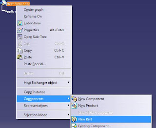
The first step is of course starting the CATIA software. By default, a product tree is opened automatically in the Assembly Design Workbench. Rename the product as Heat Exchanger. Then insert a new part into the product (right-click > Components > New Part) and name the new part as Spiral Tube.
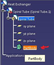
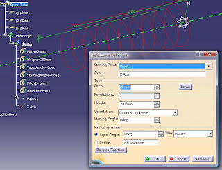
Double-click on the PartBody of the Spiral Tube to activate the Part Design Workbench. The spiral tube is to be made from a helix therefore we’ll have to use the Generative Shape Design Workbench. By keeping the Spiral Tube part selected (highlighted), select Start > Shape > Generative Shape Design. Now create a helix with starting point = (0,0,30)mm, rotation axis = x axis, pitch = 20mm, height = 200mm and left other values as default. Refer Modelling a Spring in CATIA on how to make the helix.
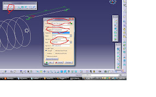
Now we’ll create 2 lines to be connected to each end of the helix. Select the end-point of the helix at (0,0,30) coordinate or the starting point of the helix. By using the line tool, create a line of 100mm as defined in the figure.
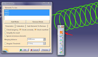
Then do the same thing to the other end of the helix. Done with that, we’ll have to join the helix and the 2 lines together and remove the corner before we can sweep the curves into a tube. To join them, use the Join tool in the Operations toolbar (or Insert > Operations > Join). Select the helix and lines for Elements to Join in the Join Definition Box. If the join is successful, the helix and lines will now be a single part. You can check in the PartBody tree.
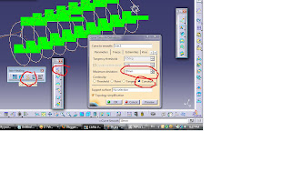
To remove the corner, we’ll use the Curve Smooth tool. In the Curve Smooth Definition box, select Join.1 for he Curve to join, set 10mm as the Maximum Deviation, and select Curvature as the Continuity type. After accepting the values, the corners will automatically be converted into curves.
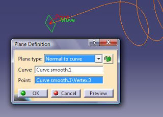
Done with the curves, go to the Part Design Workbench and create a plane at 1 end of the curves and normal to it. Check the figure.
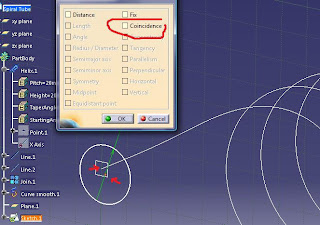
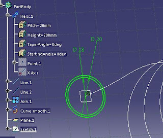
Then by selecting the new plane, draw some circles to be the inner and outer diameter of the tube. Make the outer diameter as 20mm and inner as 18mm. If somehow you get confused on where to place the center of the circles, while in the Sketcher Workbench, pan the view so that you can have a 3D look on where the end of the curve is. Then select both the end point of the curve and the center point of the circle and Coincidence them together.
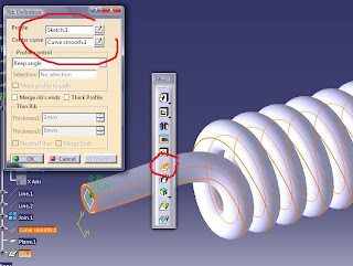
Then exit the Sketcher Workbench and back to the Part Design Workbench. Make a Rib and select Sketch.1 for the profile and Curve smooth.1 for the center curve. After pressing OK, you’ll have the Spiral Tube part. Apply Copper as Material and save the file.
To be Continued..
Copyright: CATIA V5 Tutorial
The first step is of course starting the CATIA software. By default, a product tree is opened automatically in the Assembly Design Workbench. Rename the product as Heat Exchanger. Then insert a new part into the product (right-click > Components > New Part) and name the new part as Spiral Tube.


Double-click on the PartBody of the Spiral Tube to activate the Part Design Workbench. The spiral tube is to be made from a helix therefore we’ll have to use the Generative Shape Design Workbench. By keeping the Spiral Tube part selected (highlighted), select Start > Shape > Generative Shape Design. Now create a helix with starting point = (0,0,30)mm, rotation axis = x axis, pitch = 20mm, height = 200mm and left other values as default. Refer Modelling a Spring in CATIA on how to make the helix.

Now we’ll create 2 lines to be connected to each end of the helix. Select the end-point of the helix at (0,0,30) coordinate or the starting point of the helix. By using the line tool, create a line of 100mm as defined in the figure.

Then do the same thing to the other end of the helix. Done with that, we’ll have to join the helix and the 2 lines together and remove the corner before we can sweep the curves into a tube. To join them, use the Join tool in the Operations toolbar (or Insert > Operations > Join). Select the helix and lines for Elements to Join in the Join Definition Box. If the join is successful, the helix and lines will now be a single part. You can check in the PartBody tree.

To remove the corner, we’ll use the Curve Smooth tool. In the Curve Smooth Definition box, select Join.1 for he Curve to join, set 10mm as the Maximum Deviation, and select Curvature as the Continuity type. After accepting the values, the corners will automatically be converted into curves.

Done with the curves, go to the Part Design Workbench and create a plane at 1 end of the curves and normal to it. Check the figure.

Then by selecting the new plane, draw some circles to be the inner and outer diameter of the tube. Make the outer diameter as 20mm and inner as 18mm. If somehow you get confused on where to place the center of the circles, while in the Sketcher Workbench, pan the view so that you can have a 3D look on where the end of the curve is. Then select both the end point of the curve and the center point of the circle and Coincidence them together.

Then exit the Sketcher Workbench and back to the Part Design Workbench. Make a Rib and select Sketch.1 for the profile and Curve smooth.1 for the center curve. After pressing OK, you’ll have the Spiral Tube part. Apply Copper as Material and save the file.


To be Continued..
Copyright: CATIA V5 Tutorial