
forever_young
Tài xế O-H
Pneumatic and hydraulic systems require control valves to direct and regulate the flow of fluid from compressor or pump to the various load devices. Although there are significant practical differences between pneumatic and hydraulic devices (mainly arising from differences in operating pressures and types of seals needed for gas or liquid) the operating principles and descriptions are very similar.
Although valves are used for many purposes, there are essentially only two types of valve. An infinite position valve can take up any position between open and closed and, consequently, can be used to modulate flow or pressure. Relief valves described in earlier chapters are simple infinite position valves.
Most control valves, however, are only used to allow or block flow of fluid. Such valves are called finite position valves. An analogy between the two types of valve is the comparison between an electric light dimmer and a simple on/off switch.
Connections to a valve are termed 'ports'. A simple on/off valve therefore has two
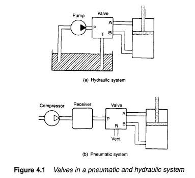
ports. Most control valves, however, have four ports shown in hydraulic and pneumatic forms in Figure 4.1.
In both the load is connected to ports labelled A, B and the pressure supply (from pump or compressor) to port E In the hydraulic valve, fluid is returned to the tank from port T. In the pneumatic valve return air is vented from port R.
Figure 4.2 shows internal operation of valves. To extend the ram, ports P and B are connected to deliver fluid and ports A and T connected to return fluid. To retract the ram, ports P and A are connected to deliver fluid and ports B and T to return fluid.

Another consideration is the number of control positions. Figure 4.3 shows two possible control schemes. In Figure 4.3a, the ram is controlled by a lever with two positions; extend or retract. This valve has two control positions (and the ram simply drives to one end or other of its stroke). The valve in Figure 4.3b has three positions;
extend, off, retract. Not surprisingly the valve in Figure 4.3a is called a two position valve, while that in Figure 4.3b is a three position valve.
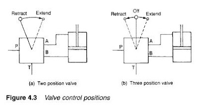
Finite position valves are commonly described as a port/position valve where port is the number of ports and position is the number of positions. Figure 4.3a therefore illustrates a 4/2 valve, and Figure 4.3b shows a 4/3 valve. A simple block/allow valve is a 2/2 valve.

The numbers of ports and positions does not, however, completely describe the valve. We must also describe its action. Figure 4.4 shows one possible action for the 4/3 valve of Figure 4.3b.
Extend and retract connections are similar, but in the off position ports P and T are connected-unloading the pump back to the tank without need of a separate loading valve, while leaving the ram locked in position. (This approach could, of course, only be used where the pump supplies one load). Other possible arrangements may block all four ports in the off position (to maintain pressure), or connect ports A, B and T (to leave the ram free in the off position).
A complete valve description thus needs number of ports, number of positions and the control action.
Graphic symbols
Simple valve symbols have been used so far to describe control actions. From the discussions in the previous section it can be seen that control actions can easily become too complex for representation by sketches showing how a valve is constructed.
A set of graphic symbols has therefore evolved (similar, in principle, to symbols used on electrical circuit diagrams). These show component function without showing the physical construction of each device. A 3/2 spool valve and a 3/2 rotary valve with the same function have the same symbol; despite their totally different constructions.
Symbols are described in various national documents; DIN24300, BS2917, ISO1219 and the new ISO5599, CETOP RP3 plus the original American JIC and ANSI symbols. Differences between these are minor.
A valve is represented by a square for each of its switching positions. Figure 4.5a thus shows the symbol of a two position valve, and Figure 4.5b a three position valve. Valve positions can be represented by letters a, b, c and so on, with 0 being used for a central neutral position.

Ports of a valve are shown on the outside of boxes in normal unoperated or initial position. Four ports have been added to the two position valve symbol shown in Figure 4.5c. Designations given to ports are normally:
Port Designation
Working lines A, B, C and so on
Pressure (power) supply P
Exhaust/Return R, S, T and so on
Control (Pilot) Lines (T normally used for hydraulic systems, R and S for
pneumatic systems) Z, Y, X and so on
ISO 5599 proposes to replace these letters with numbers, a retrograde step in the author's opinion.
Arrow-headed lines represent direction of flow. In Figure 4.6a, for example fluid is delivered from port P to port A and returned from port B to port T when the valve is in its normal state a. In state b, flow is reversed. This valve symbol corresponds to the valve represented in Figures 4.2 and 4.3a.
Shut off positions are represented by "r, as shown by the central position of the valve in Figure 4.6b, and internal flow paths can be represented as shown in Figure 4.6c. This latter valve, incidentally, vents the load in the off position.
In pneumatic systems, lines commonly vent to atmosphere directly at the valve, as shown by port R in Figure 4.6d.

 Infinite position valve symbols are shown in Figure 4.8. A basic valve is represented by a single square as shown in Figure 4.8a, with the valve being shown in a normal, or non-operated, position.
Control is shown by normal actuation symbols" in Figure 4.8b, for example, the spring pushes the valve right decreasing flow, and pilot pressure pushes the valve left increasing flow. This represents a pressure relief valve which would be connected into a hydraulic system as shown in Figure 4.8c.

Although valves are used for many purposes, there are essentially only two types of valve. An infinite position valve can take up any position between open and closed and, consequently, can be used to modulate flow or pressure. Relief valves described in earlier chapters are simple infinite position valves.
Most control valves, however, are only used to allow or block flow of fluid. Such valves are called finite position valves. An analogy between the two types of valve is the comparison between an electric light dimmer and a simple on/off switch.
Connections to a valve are termed 'ports'. A simple on/off valve therefore has two
ports. Most control valves, however, have four ports shown in hydraulic and pneumatic forms in Figure 4.1.
In both the load is connected to ports labelled A, B and the pressure supply (from pump or compressor) to port E In the hydraulic valve, fluid is returned to the tank from port T. In the pneumatic valve return air is vented from port R.
Figure 4.2 shows internal operation of valves. To extend the ram, ports P and B are connected to deliver fluid and ports A and T connected to return fluid. To retract the ram, ports P and A are connected to deliver fluid and ports B and T to return fluid.


Another consideration is the number of control positions. Figure 4.3 shows two possible control schemes. In Figure 4.3a, the ram is controlled by a lever with two positions; extend or retract. This valve has two control positions (and the ram simply drives to one end or other of its stroke). The valve in Figure 4.3b has three positions;
extend, off, retract. Not surprisingly the valve in Figure 4.3a is called a two position valve, while that in Figure 4.3b is a three position valve.

Finite position valves are commonly described as a port/position valve where port is the number of ports and position is the number of positions. Figure 4.3a therefore illustrates a 4/2 valve, and Figure 4.3b shows a 4/3 valve. A simple block/allow valve is a 2/2 valve.

The numbers of ports and positions does not, however, completely describe the valve. We must also describe its action. Figure 4.4 shows one possible action for the 4/3 valve of Figure 4.3b.
Extend and retract connections are similar, but in the off position ports P and T are connected-unloading the pump back to the tank without need of a separate loading valve, while leaving the ram locked in position. (This approach could, of course, only be used where the pump supplies one load). Other possible arrangements may block all four ports in the off position (to maintain pressure), or connect ports A, B and T (to leave the ram free in the off position).
A complete valve description thus needs number of ports, number of positions and the control action.
Graphic symbols
Simple valve symbols have been used so far to describe control actions. From the discussions in the previous section it can be seen that control actions can easily become too complex for representation by sketches showing how a valve is constructed.
A set of graphic symbols has therefore evolved (similar, in principle, to symbols used on electrical circuit diagrams). These show component function without showing the physical construction of each device. A 3/2 spool valve and a 3/2 rotary valve with the same function have the same symbol; despite their totally different constructions.
Symbols are described in various national documents; DIN24300, BS2917, ISO1219 and the new ISO5599, CETOP RP3 plus the original American JIC and ANSI symbols. Differences between these are minor.
A valve is represented by a square for each of its switching positions. Figure 4.5a thus shows the symbol of a two position valve, and Figure 4.5b a three position valve. Valve positions can be represented by letters a, b, c and so on, with 0 being used for a central neutral position.

Ports of a valve are shown on the outside of boxes in normal unoperated or initial position. Four ports have been added to the two position valve symbol shown in Figure 4.5c. Designations given to ports are normally:
Port Designation
Working lines A, B, C and so on
Pressure (power) supply P
Exhaust/Return R, S, T and so on
Control (Pilot) Lines (T normally used for hydraulic systems, R and S for
pneumatic systems) Z, Y, X and so on
ISO 5599 proposes to replace these letters with numbers, a retrograde step in the author's opinion.
Arrow-headed lines represent direction of flow. In Figure 4.6a, for example fluid is delivered from port P to port A and returned from port B to port T when the valve is in its normal state a. In state b, flow is reversed. This valve symbol corresponds to the valve represented in Figures 4.2 and 4.3a.
Shut off positions are represented by "r, as shown by the central position of the valve in Figure 4.6b, and internal flow paths can be represented as shown in Figure 4.6c. This latter valve, incidentally, vents the load in the off position.
In pneumatic systems, lines commonly vent to atmosphere directly at the valve, as shown by port R in Figure 4.6d.

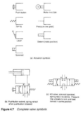
Figure 4.7a shows symbols for the various ways in which valves can be operated. Figure 4.7b thus represents a 4/2 valve operated by a pushbutton. With the pushbutton depressed the ram extends. With the pushbutton released, the spring pushes the valve to position a and the ram retracts.
Actuation symbols can be combined. Figure 4.7c represents asolenoid-operated 4/3 valve, with spring return to centre.
Actuation symbols can be combined. Figure 4.7c represents asolenoid-operated 4/3 valve, with spring return to centre.
 Infinite position valve symbols are shown in Figure 4.8. A basic valve is represented by a single square as shown in Figure 4.8a, with the valve being shown in a normal, or non-operated, position.
Control is shown by normal actuation symbols" in Figure 4.8b, for example, the spring pushes the valve right decreasing flow, and pilot pressure pushes the valve left increasing flow. This represents a pressure relief valve which would be connected into a hydraulic system as shown in Figure 4.8c.